IMAGE QUALITY INDICATORS
Image quality indicator (IQI), also called penetrameter is a device used to judge the quality of radiography. This is measured in terms of radiographic sensitivity. smaller the numerical value of radiographic sensitivity. better the radiographic quality. Image quality indicators are of simple geometric form and made of the same or similar material as the specimen being examined. The image of the IQI on the radiograph is permanent evidence that the radiographic inspection was conducted under proper conditions.
A number of IQI designs are used by different authorities in the world. There are American Standards, British standards, French, German, International and Indian standards. Some of the most commonly used IQI designs are mentioned below.
Step Type
This is the simplest of penetrameters. It consists of steps of 0.5 to 5%. of specimen thickness and is made of the same or similar material of the specimen. Sensitivity is determined by the thickness of the step that is perceptible in the radiograph. This type of penetrameters essentially provides contrast sensitivity. This is shown in Figure 1.
Hole-Step Penetrameter
This design IS similar to that of the step penetrameters but includes one or two drilled holes in each step.
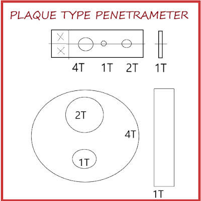
Plate Type Penetrometers
The widely used American Penetrometers are those that follow the ASTM and ASME
Recommended designs. This made up of a plate of uniform thickness in which three drilled
holes of diameters equal to 1 T, 2 T, 3 T, and 4 Tare are made (This is equal to the thickness of the penetrometer).
Identification of numbers and letters which specify the material and specimen thickness for which it is intended is fixed to each plate. The details of the design and the useful range of this class of penetrometers are given in figure 2. The ASTM Penetrameters have drilled holes of 1 T, 2 T, and 4 T. The thickness of each penetrameter is fashioned on the levels of sensitivity desired. A one percent penetrameter is one in which the thickness of penetrameter corresponds to 1% of the specimen thickness, a two percent penetrameter is the one which has
2% of the specimen thickness.
Material Thickness, IQI Designations, and Essential Holes
NominalSingle wall Source side Film side
material thickness
range In Inches Number, Hole, Wire Number, Hole, Wire
Upto 0.25 incl. 12 2 T 0.008 10 2 T 0.006
Over 0.25 to 0.375 15 2 T 0.010 12 2 T 0.008
Over 0.375 to 0.5 17 2 T 0.013 15 2 T 0.010
Over 0.5 to 0.75 20 2 T 0.016 17 2 T 0.013
Over 0.75 to 1.0 25 2 T 0.020 20 2 T 0.016
Over 1.0 to 1.5 30 2 T 0.025 25 2 T 0.020
Over 1.25 to 2.0 35 2 T 0.032 30 2 T 0.025
Over 2.0 to 2.5 40 2 T 0.040 35 2 T 0.032
Over 2.5 to 4.0 50 2 T 0.050 40 2 T 0.040
Over 4.0 to 6.0 60 2 T 0.063 50 2 T 0.050
Over 6.0 to 8.0 80 2 T 0.100 60 2 T 0.063
Over 8.0 to 10.0 100 2 T 0.126 80 2 T 0.100
Over 10.0 to 12.0 120 2 T 0.160 100 2 T 0.126
Over 12.0 to 16.0 160 2 T 0.250 120 2 T 0.160
Over 16.0 to 20.0 200 2 T 0.320 160 2 T 0.250
DIN penetrameter set can be selected by knowing the wire diameter corresponding to specimen thickness.
I.Q.I PLACEMENT
The JQI should be placed as far as possible on the source side of the radiation. When it is not possible to do so, as in the case of double-wall single image radiography, it can be kept on the film side in which case, lead letter F must be placed near the IQI. The location of the 101 should be such that it must be in the most unfavorable location with respect to
the radiation beam. The general recommendations are :
In the case of welds, wire type IQI shall be kept across the weld and step wedge and strip hole type parallel to the weld 1/8" away from the weld edge.
A minimum of one IQI per radiograph Is necessary. However, if a circumferential weld Is covered by panoramic technique, 4 IQI = 90° apart are sufficient.
When there is a difference in thickness, and if this difference exceeds the range of one IQI, more than one IQI is required.
In the case of welds with a backing ring or with excessive reinforcement/excess penetration, while using step wedge/ strip hole type of IQI, a shim has to be used.
When the density of the radiograph varies from the location of IQI by more than -15% to
+30%, then another IQI is required for the second density.
When it is not possible to place the penetrameter on the specimen, it can be placed on a separate block of the radiographically similar material and of the same thickness.
SENSITIVITY CALCULATIONS
Wire Type IQI
Sensitivity % = (Diameter of the thinnest visible wire x 100) / Thickness of the object
Step - hole Type IQI
Step - hole Type IQI
Sensitivity % = ( Dia.of the smallest visible Hole x 100) / Thickness of the object
Plate hole Type (ASTM Type)
In this type, the penetrameter image and the specified hole are the essential indications of sensitivity. The thickness of the penetrameter and the hole diameter to be seen is generally specified in the code. Normally, the image of 2 T hole for 2%. thickness of JQJ (2 -2n should be visible in the radiograph. Critical components required a level of 1-2T or 1-1T. Less critical components may need only a quality level of 2-4T or 4-4T. The more critical the radiographic examination is, the higher the level of radiographic sensitivity required and the lower the numerical designation for the quality level. The following are the different sensitivity levels of inspection with strip hole type JQI.
1-1T 2-2T 4-4T
2 -2T 2- 2T 4-2T
1 -4T 2 -4T 4-4T
Wire Type Penetrameters
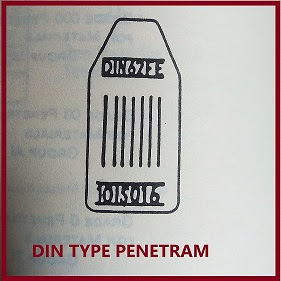
DIN TYPE
The German and the International institute welding have proposed a series of wired in place of plates of varying thickness of plates with different steps in them, for image quality indicators. The wires are made of aluminum or steel or of material similar to that of an object under inspection. The DIN (German design - The Doutscho Industries Normal) are graded in geometrical progression designation from 1-16, the first number wire having diameter 3.2 mm and the sixteenth wire having 0.10 mm. Each wire is about 5 cms long. A set of 7 wire 5 mm apart, is sealed rigidly in a flexible plastic or rubber envelope. The ratio between the thickness of adjacent wires is 1.25 in image quality indicator
WIRE DIAMETER OF PENETRAMETERS-
1-ISO-7 (wire dia in mm)
3.2
2.5
2.0
1.6
1.25
1.0
0.80
6-ISO-12
1.0
0.8
0.63
0.5
0.4
0.32
0.25
10-ISO-16
0.4
0.32
0.25
0.2
0.16
0.13
0.10
ASTM TYPE
This design as shown in sketch consists of 4 sets of wires having diameters from
0.0032 mm to o.32 mm. Each set has 6wires with last wire of the previous set being repeated as the 1st wire of the next set. The penetrameter is designed and characterized by its simplicity and ease
of application, independence to beam orientation. The design accounts for, to some extent, definition or unsharpness and contrast factors, particularly related to linear volume elements. Here again, as in other designs of penetrameters, unsharpness factors are not independently evaluated. And there is no defined relationship between the sensitivity levels obtained by wire types and step type or plate type penetrameters (image quality indicator).
WIRE DIAMETER IN INCH
SET A
0.0032
0.004
0.005
0.0063
0.008
0.010
SET B
0.010
0.013
0.016
0.020
0.025
0.032
SET C
0.032
0.040
0.050
0.063
0.080
0.100
SET D
0.100
0.126
0.160
0.200
0.250
0.320
Indian Standards Institution - Penetrameter Design
The Indian Standards Institution has recommended the design of bot wire type and hole-step type penetrameters (image quality indicator). These designs have not become popular for obvious reasons. Other designs of penetrameters are readily available in India and do not differ materially from Indian Standards.


No comments:
Post a Comment
Please do not enter any spam link in the comment box