QA–QC BYUNS – Note – "This site uses cookies from Google to deliver its services to personalize ads and to analyze traffic information about your use of this site is shared with Google, BY USING THIS SITE YOU AGREE TO ITS USE OF COOKIES"

Sunday, February 28, 2021

फ़्लोचार्ट्स (Flow Charts)

 फ़्लोचार्ट्स (Flow Charts)

flow charts


फ़्लोचार्ट्स को अक्सर जटिल काम के क्रम को और गतिविधियों केआंतरिकसम्बन्ध का एक आसान समझने वाला अवलोकन देने के लिए डिज़ाइन किया जाता है। आयत, हीरे और अन्य आकृतियों का उपयोग काम के स्टेज , जैसे गतिविधियों, निर्णयों और दस्तावेजों को चित्रित करने के लिए किया जाता है। ये आकृतियाँ एरो द्वारा जुड़ी होती हैं जो प्रवाह और क्रम को दर्शाती हैं।

निम्नलिखित आकृतियाँ या प्रतीक फ़्लोचार्ट को समझने के लिए पर्याप्त है।  


flow charts


इस आकृति का उपयोग किसी प्रक्रिया या गतिविधि को चित्रित करने के लिए किया जाता है। एरो इनपुट और आउटपुट का संकेत देते हैं।


FLOW CHART
इस आकृति का उपयोग किसी निर्णय का वर्णन करने के लिए किया जाता है। फ्लोचार्ट में एक निर्णय में आमतौर पर दो या अधिक परिणाम होते हैं। उदाहरण में, निर्णय दो संभावित परिणाम "हाँ" और "नहीं" हो सकता है।


flow charts


यह आकृति एक दस्तावेज़ (रिकॉर्ड) का वर्णन करता है। जहाँ भी रिकॉर्ड की बात हो, इस आकृति का उपयोग किया जाता है।


Wednesday, February 24, 2021

Selection of Stick Electrodes

 सही 'स्टिक इलेक्ट्रोड' का चयन

Selection of Stick Electrodes

SELECTION OF STICK ELECTRODE

Welding rod selection

स्टिक इलेक्ट्रोड विभिन्न यांत्रिक गुणों के साथ उपलब्ध हैं और यह एक विशिष्ट शक्ति स्रोत के साथ संचालित होता है। वेल्डिंग रॉड चयन में विचार किए जाने वाले कारक निम्नलिखित हैं:

Tensile strength

Base metal properties

Welding current

Base metal thickness, shape, and joint fit-up

Welding position

Specification and service conditions

Environmental job conditions

Tensile strength

Match the minimum tensile strength of the electrode with the tensile strength of the base metal. This can be identified by referring first 2 digits of the AWS classification of the electrode. For example, the number “70” on an E7018 electrode indicates that filler metal produces a weld bead with a minimum tensile strength of 70,000 psi and, would work with steel of similar tensile strength.

Base metal properties

The first step is to determine base metal composition than its mechanical properties.

• धातु कैसे दिखता है? यदि टूटे हुए भाग या घटक में मोटे और दानेदार आंतरिक सतह होती है, जिसका अर्थ है कि आधार सामग्री एक कच्चा धातु है।

• धातु चुंबकीय है? यदि बेस मेटल चुंबकीय है, तो संभावना है कि बेस मेटल कार्बन स्टील या मिश्र धातु स्टील है। यदि आधार धातु चुंबकीय नहीं है, तो सामग्री मैंगनीज स्टील, सहायक स्टेनलेस स्टील या एल्यूमीनियम, पीतल, तांबा या टाइटेनियम जैसे अलौह मिश्र धातु हो सकती है।

• एक ग्राइंडर द्वारा छुआ जाने पर धातु किस तरह की चिंगारियां देती है? अंगूठे के एक नियम के रूप में, स्पार्क में अधिक भड़कना उच्च कार्बन सामग्री को इंगित करता है जैसे कि ए -36 ग्रेड स्टील।

• बेस मेटल में छेनी "काटता है" या उछलता है? एक छेनी नरम स्टील या एल्यूमीनियम जैसे नरम धातु में काटेगी, और उच्च कार्बन स्टील, क्रोम-मोली या कच्चा लोहा जैसे कठोर धातुओं से उछल जाएगी।

Welding current

Current type:-

Depending upon the 4th digit of an electrode’s AWS classification, the current type can find out. It is based on the type of coating available on the electrode (see below figure).

4th Digit Type of Coating Welding Current

0         Cellulose sodium       DCEP

1        Cellulose potassium      AC or DCEP

2        Titania sodium             AC or DCEP

3        Titania potassium       ALL

4        Iron powder titania     ALL

8       Iron powder low hydrogen  AC or DCEP

DCEP- DIRECT CURRENT ELECTRODE POSITIVE,

DCEN- DIRECT CURRENT ELECTRODE NEGATIVE,

DCEP compatible electrode influences the penetration profile of the resulting weld. DCEP compatible electrode delivers deep penetration and produces an excellent arc. DCEN suitable (compatible) electrode provides light penetration and works well when welding high speed, high current fillet welds in the horizontal position.

An AC-compatible electrode can produce a soft arc with medium penetration of weld and can be used to weld sheet metal.

Base metal thickness, shape, and joint fit-up

Welding of thick materials needs an electrode that has maximum ductility and low hydrogen to prevent cracking. Electrodes with good toughness (high impact values) can accommodate for residual stress.

Welding position

The third digit in AWS classification of a particular electrode tells about its positional qualification. For exam- a 7018 electrode can be used in the flat, horizontal, vertical, and overhead positions.

1 = flat, horizontal, vertical, and overhead

2 = flat and horizontal only

Specification and service conditions

Take into consideration of its use- high heat, low temperature, repetitive shock loading, and pressure vessel or boiler fabrication. AND

Environmental job conditions


Thursday, February 18, 2021

Plasma Cutting

Plasma Cutting कैसे काम करता है? फायदे नुकसान

प्लाज्मा कटिंग एक थर्मल कटिंग विधि है जहां धातु को काटने के लिए आयनित गैस का उपयोग किया जाता है। यह मोटी धातु प्लेटों को काटने के लिए सबसे व्यापक रूप से इस्तेमाल की जाने वाली तकनीकों में से एक है, लेकिन शीट धातु के लिए भी उपलब्ध है।

Plasma Cutting


प्लाज्मा क्या है?

पदार्थ की तीन मूलभूत अवस्थाएँ हैं - ठोस, तरल और गैस, लेकिन एक चौथा भी है, यह प्लाज्मा है।

हमारे दैनिक जीवन में, हम टीवी, फ्लोरोसेंट लैंप, नियॉन संकेत और प्लाज्मा कटर में प्लाज्मा पा सकते हैं।

प्लाज्मा एक विद्युत प्रवाहकीय आयनीकृत पदार्थ है।

एक गैस को तीव्र ताप द्वारा प्लाज्मा में परिवर्तित किया जा सकता है, इसलिए प्लाज्मा को आयनित गैस भी कहा जाता है।

प्लाज्मा एक गैस की तरह होता है क्योंकि परमाणु एक दूसरे के निरंतर संपर्क में नहीं होते हैं। जब यह एक विद्युत और चुंबकीय क्षेत्र के अधीन होता है तो यह तरल पदार्थों के समान व्यवहार करता है।

प्लाज्मा कटर संपीड़ित हवा, ऑक्सीजन और नाइट्रोजन का उपयोग करता है। प्लाज्मा बनाने के लिए गैसों का आयनिकरण होता है।

संपीड़ित गैसें इलेक्ट्रोड के संपर्क में आती हैं और फिर अधिक दबाव बनाने के लिए आयनित होती हैं। जब दबाव बनाया जाता है, तो प्लाज्मा की एक धारा को काटने वाले सिर की ओर धकेल दिया जाता है।

काटने की नोक प्लाज्मा की एक धारा बनाने के लिए प्रवाह को रोकती है। चूंकि प्लाज्मा विद्युत प्रवाहकीय होता है, काम का टुकड़ा कटिंग टेबल के माध्यम से जमीन से जुड़ा होता है।

जैसा कि प्लाज्मा चाप धातु से संपर्क करता है, इसका उच्च तापमान इसे पिघला देता है। इसी समय, उच्च गति गैसें पिघली हुई धातु को उड़ा देती हैं।

फायदे नुकसान

लाभ

सभी प्रवाहकीय सामग्रियों को काटने में सक्षम। हालांकि, मोटी धातुओं को काटने के लिए उपयुक्त फ्लेम कटिंग केवल लौह धातुओं तक सीमित है।

50 मिमी तक की मोटाई के लिए महान गुणवत्ता।

अधिकतम मोटाई 150 मिमी तक।

मध्यम मोटाई में कटौती के लिए तुलनात्मक रूप से सस्ता है।

मध्यम मोटाई वाले स्टेनलेस स्टील और एल्यूमीनियम को काटने का सबसे अच्छा तरीका।

उच्च परिशुद्धता और पुनरावृत्ति प्रदान करने के लिए सीएनसी मशीनें उपलब्ध हैं।

पानी में कटौती कर सकते हैं, जिसके परिणामस्वरूप छोटे HAZ। शोर के स्तर को भी कम करता है।

ऑक्सीफ़्यूल की तुलना में तेज़ गति।

नुकसान

लेजर कटिंग की तुलना में बड़ा HAZ।

पतले शीट्स और प्लेट्स के साथ क्वालिटी जो लेजर कटिंग जितनी अच्छी नहीं है।

लेज़र कटिंग जितना सही नहीं है, टॉलरेंस।

वॉटरजेट या फ्लेम कटिंग जैसी मोटाई तक नहीं पहुंचता है।

एक HAZ छोड़ता है जो वॉटरजेट नहीं करता है।

लेजर कटिंग की तुलना में विडर केर्फ।

एक काटने विधि का चयन

अलग-अलग काटने के तरीकों के बीच अपनी पसंद बनाना सामग्री, उसकी मोटाई और भागों के आवेदन के लिए नीचे आता है।

प्लाज्मा कटिंग के लिए अनुशंसित कटिंग की मोटाई 15… 50 मिमी के बीच है।

प्लाज्मा कटिंग सेवा के लिए सामग्री की मोटाई की अनुशंसित ऊपरी सीमा कार्बन और स्टेनलेस स्टील के लिए लगभग 50 मिमी है। एल्यूमीनियम को 40 मिमी से आगे नहीं जाना चाहिए।

ऊपर सब कुछ है कि वॉटरजेट और लौ काटने के क्षेत्र में है।

लेजर कटिंग सेवाओं को शीट मेटल और थिनर प्लेट्स के लिए पसंदीदा विकल्प होना चाहिए क्योंकि यह अधिक है

 काटने की गुणवत्ता और गति। लेकिन लेजर कटिंग की ऊपरी सीमा लगभग 25… 30 मिमी है।

प्लाज्मा कटिंग तेज है और 15 मिमी से शुरू होने वाली प्लेटों के साथ सस्ता है।

Plasma Cutting


Sunday, February 14, 2021

CROSSWORD PUZZLE

 THE EIGHT DISCIPLINES (8D) CROSSWORD PUZZLE

CROSSWORD PUZZLE

Dear QC Engineers, hope you all are doing well.
Here is the post in the EIGHT DISCIPLINES (8D) CROSSWORD series.

Let's test your QC knowledge. 💪


Ans:

                   Horizontal                                                        
1D: Team Formation                                      
2D: Problem Description                               
4D: Root Cause Analysis                               
8D: Team and individual recognition            

                 Vertical
3D: Interim Containment Action
5D: Corrective Actions
6D: Verification of Corrective Actions
7D: Preventive Actions

keep learning, keep sharing, and yes, stay safe.😊

Tuesday, February 9, 2021

Inspection Table

 What is Inspection Table?

It's a table where the Inspection Execution environment is configured for Inspection.

Before we (Inspector) start the Inspection, it is highly important to ensure that the Inspection Table (Inspection Tools, Marker, Configuration setup, Test Data, Reference Documents and Peoples related to the job, and anything else that can contribute for Inspection) is set up appropriately. It helps us to keep the focus on Inspection (rather than dealing with the issues which slow down the Inspection activities).

Below is the Mind Map created about Inspection Table.

Inspection Table
Mind Map

Note: Additional information can be added in the above mind map. Feel free to comment below with your inputs.👍

Keep learning, please keep sharing, and stay safe.👌

Wednesday, February 3, 2021

Tolerance and fits

Tolerance and fits

 Limits and fits table

Tolerance and Fits
tolerance and fits


Limits & Fits

In the mechanical engineering, a fit is clearance between two mating parts. The choice of the fit in case of a clearance fit, defines whether two parts can move relative to each other, or act as a single part, in case of a tight interference fit.
Limits and fits applies to all mating parts, main use is to regulate the sizes of mating shafts and holes to achieve best performance.
ISO and ANSI both have standardised fits that is in three classes – Clearance, Transition & Interference. Each class have variety of options available for choosing the correct one for a specific application.

Hole and Shaft Basis System

There are two type of fit system – hole and shaft system. The system defines which part have a controlled measurement and other part is made based on it.

Hole-basis system - constant measurement for the hole and diameter of shaft is made accordingly to achieve the required fit.

Shaft-based system - vice-versa.

In engineers mostly follow the hole system because of its simplicity. Here hole size remains constant, and shaft upper and lower deviation values defines type of fit. Limits & Fits

Tolerance of parts are defined to ensure a proper working of a machine. Fits can be chosen according to the working condition. There are three main categories:

Clearance fit

Transition fit

Interference fit

 A clearance fit always leaves space between two parts. A transition fit is in between clearance fits and interference fits. An interference fit is tight or press fit for easing the required process.

Clearance Fits

With this fit, shaft is always smaller than hole size. This enables easy of assembly and keeps space for sliding and rotational parts.

Transition Fits

In the transition fit the shaft may be a little bigger than hole to require some force to create the fit.

Interference Fits

Interference fits are press fits or friction fits. These types of fits always have larger shaft compared to the hole size.

Limits & Fits

इंजीनियरिंग में, एक फिट दो mating भागों के बीच clearance को संदर्भित करता है। एक इंजीनियरिंग फिट की पसंद यह निर्धारित करती है कि क्लीयरेंस फिट होने की स्थिति में दोनों हिस्से एक-दूसरे के सापेक्ष आगे बढ़ सकते हैं या एक तंग हस्तक्षेप के मामले में एक पूरे के रूप में कार्य कर सकते हैं।
जबकि सीमा और फिट सभी प्रकार के MATING भागों पर लागू होते हैं, उनका मुख्य उपयोग MATING के आकार और छेद को सर्वश्रेष्ठ प्रदर्शन के लिए विनियमित करने के लिए है।
आईएसओ और एएनएसआई दोनों ने तीन वर्गों में मानकीकृत फिट किए हैं - निकासी, संक्रमण और हस्तक्षेप। प्रत्येक वर्ग के पास एक विशिष्ट आवेदन के लिए सही चुनने के लिए विभिन्न प्रकार के विकल्प उपलब्ध हैं।

Hole and Shaft Basis System
फिट के लिए एक सिस्टम चुनते समय, आपके पास 2 विकल्प होते हैं - छेद और शाफ्ट सिस्टम। सिस्टम बताता है कि किस हिस्से में नियंत्रित माप है और कौन सा हिस्सा दूसरे के आधार पर बनाया गया है।
संक्षेप में, छेद-आधार प्रणाली छेद के लिए एक निरंतर माप का उपयोग करती है और शाफ्ट के व्यास को आवश्यक फिट प्राप्त करने के लिए तदनुसार बनाया जाता है।
और शाफ्ट-आधारित प्रणाली इसके विपरीत काम करती है।
इंजीनियर सादगी के कारण छेद प्रणाली का पालन करते हैं। जैसा कि छेद का आकार स्थिर रहता है, शाफ्ट के ऊपरी और निचले विचलन मूल्य फिट के प्रकार को निर्धारित करते हैं। ड्रिलिंग अधिक सटीकता की अनुमति नहीं देती है, क्योंकि टूलींग कुछ मापों में आती है।
सीमा और फिट
सीमा और फिट बैठता है टेबल
इंजीनियरिंग में, हमें एक मशीन के लंबे जीवनकाल और उचित कार्य को सुनिश्चित करने के लिए भागों की सहनशीलता को परिभाषित करना होगा। हम आवश्यकताओं और काम की परिस्थितियों के अनुसार फिट का चयन कर सकते हैं। तीन मुख्य श्रेणियां हैं:
क्लीयरेंस फिट
संक्रमण फिट
हस्तक्षेप फिट
ये सभी श्रेणियों के एक अन्य सबसेट के साथ आते हैं, प्रत्येक को विभिन्न परिस्थितियों के लिए डिज़ाइन किया गया है। बेशक, हमें यह ध्यान रखना होगा कि निकटता और अधिक स्नॉग फिट होने के कारण मशीनिंग सटीकता पर उच्च मांगों और असेंबली की कठिनाई के कारण उच्च लागत होगी।
एक निकासी फिट हमेशा दो हिस्सों के बीच में जगह छोड़ती है। एक संक्रमण फिट कहीं निकासी फिट और हस्तक्षेप फिट के बीच है और किसी भी तरह से समाप्त हो सकता है लेकिन बहुत तंग होने के लिए बहुत जगह छोड़ने के बिना। एक हस्तक्षेप फिट तंग है और फिट बनाने के लिए प्रक्रिया को आसान बनाने के लिए काफी बल और अन्य तकनीकों की आवश्यकता होती है।
निकासी फिट बैठता है
एक निकासी फिट के साथ, शाफ्ट हमेशा छेद से छोटा होता है। यह स्लाइडिंग और घूर्णी आंदोलन के लिए आसान विधानसभा और पत्तियों के कमरे को सक्षम करता है।
संक्रमण फिट बैठता है
एक संक्रमण फिट दो संभावनाओं को शामिल करता है। शाफ्ट छेद से थोड़ा बड़ा हो सकता है, जिससे फिट बनाने के लिए कुछ बल की आवश्यकता होती है। स्पेक्ट्रम के दूसरे छोर पर आंदोलन के लिए थोड़ी सी जगह के साथ एक निकासी फिट है।
हस्तक्षेप फिट बैठता है
हस्तक्षेप फिट को प्रेस फिट या घर्षण फिट के रूप में भी जाना जाता है। इस प्रकार के फिट में हमेशा छेद आकार की तुलना में एक बड़ा शाफ्ट होने का एक ही सिद्धांत होता है।


Friday, January 1, 2021

use of Environ("USERPROFILE") in excel vba

 use of Environ("USERPROFILE") in excel vba

ENVIRON

How to make a path as dynamic by using ENVIRON


IF path= E:\Redirect\un.singh\Desktop then I can make it dynamic BY use of vba by replacing "E:\Redirect\un.singh" with Environ("USERPROFILE") & \Desktop 

one simple example is as under-

Sub hyper_link()
Dim FileName, mystore As String
Dim PathName As String, i As Long
'AUTO SELECT USER DESKTOP NAME
PathName = Environ("USERPROFILE") & "\Desktop\ALL DRGS\"
FileName = Dir(PathName & "*.pdf")
    Do While FileName <> vbNullString
        mystore = Mid(FileName, 5, 8)
        On Error GoTo last:
'COMPARE MYSTORE FOR ALL CELLS OF COLUMN "B"
    For i = 2 To 374
        If mystore = Left(Range("B" & i).Value, 8) Then
            Range("B" & i).Select
            ActiveSheet.Hyperlinks.Add Range("B" & i), Address:=(PathName & FileName)
        Else: End If
    Next i
'NEXT FILE FOR MYSTORE
FileName = Dir
    Loop
last:
End Sub


Sunday, April 12, 2020

EXCEL VBA, USE OF COMPID, FSO AND INPUTBOX

Option Explicit
-------------------------------------------
Sub findfileinfolder()

Call CountFiles

End Sub
---------------------------------------------
Private Function CountFiles()
Dim strDirectory As String, strDestFolder As String, strExt As String

strDirectory = InputBox("pl inter path for serch folder")

'strDestFolder = InputBox("pl inter path for output folder")

    Dim myfilesystemobject As Object
    Dim myfiles As Object
    Dim myFile As Object
    Dim Compld As Range
    Dim mystore As Variant
   
    Set myfilesystemobject = CreateObject("Scripting.FileSystemObject")
    Set myfiles = myfilesystemobject.GetFolder(strDirectory).Files
   
    For Each myFile In myfiles
           
       Range("B1").ClearContents
       Range("B1").Value = myFile.Name
       mystore = myFile.Name
       
        Set Compld = Range("A:A").Find(what:=mystore, LookIn:=xlValues, lookat:=xlWhole)
                   
            If Not Compld Is Nothing Then
            'Stop
                 With myFile
                    .Copy strDestFolder & "\" & myFile.Name
                 End With
            Else
            End If
         
    Next myFile
     
    Set myfiles = Nothing
    Set myfilesystemobject = Nothing
End Function


Wednesday, April 1, 2020

Metal transfer modes in GMAW

Metal transfer modes in GMAW

Metal transfer modes in GMAW

Globular 
Globular  मेटल ट्रांसफर के साथ GMAW को तीन प्रमुख GMAW विविधताओं में से सबसे कम वांछनीय माना जाता है, क्योंकि इसकी उच्च गर्मी, खराब वेल्ड सतह और स्पैटर का उत्पादन करने की प्रवृत्ति है। विधि को मूल रूप से GMAW का उपयोग करके स्टील को वेल्ड करने के लिए एक लागत-कुशल तरीके के रूप में विकसित किया गया था क्योंकि यह भिन्नता कार्बन डाइऑक्साइड का उपयोग करती है, जो आर्गन की तुलना में एक कम महंगा परिरक्षण गैस है। जिससे 110 मिमी / एस (250 / मिनट) तक की वेल्डिंग गति की अनुमति दी जा सकती थी। जैसा कि वेल्ड किया जाता है, इलेक्ट्रोड से पिघली हुई धातु की एक गेंद इलेक्ट्रोड के अंत में निर्मित होती है, अक्सर इलेक्ट्रोड की तुलना में एक बड़े व्यास के साथ अनियमित आकार में होती है। जब छोटी बूंद या तो गुरुत्वाकर्षण या लघु-चक्कर द्वारा समाप्त हो जाती है, तो यह असमान सतह को छोड़ कर अक्सर स्पैटर का कारण बन जाती है। बड़ी पिघली हुई छोटी बूंद के परिणामस्वरूप, प्रक्रिया आमतौर पर फ्लैट और क्षैतिज वेल्डिंग पदों तक सीमित होती है, इसके लिए मोटे वर्कपीस की आवश्यकता होती है, और एक बड़े वेल्ड पूल में परिणाम होता है।

Ultrasonic Testing of Welds on Plates

Ultrasonic Testing of Welds on Plates

Ultrasonic Testing of Welds on Plates

For testing a weld satisfactorily, the following information should be available
(i) Material, (ii). Details of weld preparation, (iii). Welding process and probable defects expected, (iv) Applica­tion of the part and (v)Acceptance criteria.

Testing of a single 'V'butt joint welded only from one side using transverse waves.
The selection of probe frequency depends on the flaw to be detected and attenuation in the effects of the near zone and beam spread the minimum size of the material. Which varies with frequency should be considered. For mild steel welds usually, a frequency in the range of 1 MHz to 4 MHz will be satisfactory.

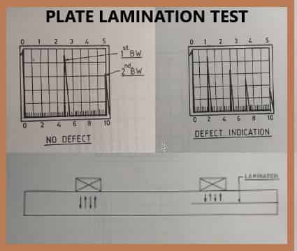
Ultrasonic Testing for laminations in plates

Ultrasonic Testing for laminations in plates 

Ultrasonic Testing for laminations in plates

Ultrasonic Testing for laminations in plates - A normal probe is brought into contact with the face of the plate through a couplant. The height of the back wall echo is kept at a fixed amplitude (50% or above F.S.H.)

Any drop  1n  back wall echo is considered to be caused by defective area.   Usually, the plate is scanned along grid lines only and wherever the back wall echo falls beyond a  set level or when a defect indication is present,  the adjacent area is also scanned to determine the area of defect.   Some­ times angle beam technique is also used to detect the presence of defects that are not oriented parallel to the surface.

Tuesday, March 31, 2020

FORGING PROCESS

FORGING PROCESS

FORGING PROCESS

1.INTRODUCTION
Forging is a metal mass that has been worked or brought to a configuration attained by controlled plastic deformation, by hammering, pressing, upsetting, rolling extruding, etc. Aluminum, Copper and their alloys, steels, titanium and many other alloys can be forged.
Forging can be produced either by hot working or cold working.

CASTING PROCESS

CASTING PROCESS

CASTING PROCESS


1.INTRODUCTION


The basic of casting processes Is feeding of molten metal Into a cavity of the required shape In a mould, followed by cooling to produce a solid object. The various processes differ principally In the way In which tho mould Is formed. In some cases e.g., sand moulding, a mould Is made up for each cast and subsequently broken up to remove the casting. In other cases, e.g., die casting, a permanent mould Is used repeatedly for a succession of casts and the casting Is removed after each cast without damage to the mould. Provision Is made for the feeding of the casting by forming a gating system in the mould. At the same time, an enlarged opening (a pouring cup) Is made to enable easy pouring, and channels are cut to allow the metal to flow out of the mould cavity after filling it, thus maintaining a metallostaUc head during solidification.

Monday, March 30, 2020

GMAW WELDING PROCESS

GMAW WELDING PROCESS

GMAW WELDING PROCESS

GAS METAL ARC WELDING (GMAW)
In this process, an arc is maintained in a stream of inert gas between a consumable electrode and the workpiece. The arc heats the work and melts the electrode, which thus supplier filler metal for the joint.   The power sources used are direct current with electrode positive.   The metal transfer is irregular if the electrode is negative or if the alternating current is the use of whilst effective welding of aluminum is only possible if the workpiece is negative so that oxide film is removed by the action of the arc cathode.

Arc Welding with Coated Electrode (SMAW)

Arc Welding with Coated Electrode

Arc Welding with Coated Electrode

Arc welding is carried out by striking an arc between a rod electrode and the workpiece, thus simultaneously heating the workpiece and melting the electrode, which supplies filler metal for the joint. The power supply used In welding with coated electrodes consists of a DC or AC source with a dropping characteristic.

Sunday, March 29, 2020

SOME RADIATION CALCULATION FORMULAS AND EXAMPLES

SOME RADIATION CALCULATION FORMULAS AND EXAMPLES

SOME RADIATION CALCULATION FORMULAS AND EXAMPLES

SOURCE TO FILM DISTANCE CALCULATION

SFD (min)= t(1+d/ug)

t= thickness of job
d= source size
ug= 0.5 max

INTRODUCTION TO NON- DESTRUCTIVE TESTING (NDT)

NDT

INTRODUCTION TO NON- DESTRUCTIVE TESTING

INTRODUCTION

Non-destructive testing (NDT) Is a  method of quality control of materials without disturbing their aimed use.  The material under Inspection does not undergo any change In Its size, shape, physical and chemical properties. It is commonly used for:

Detection of flaws such as cracks, shrinkages, gas porosities, inclusions, and another weld, forging and casting defects.
Determining the material characteristics such as density, conductivity, hardness, grain structures, etc. to give clues about the strength of materials.
Dimensional measurements such as wall thickness, internal and outside dimensions, corrosion assessment coating/plating thickness, etc.
On-line monitoring of plants/ industrial systems.

IMAGE QUALITY INDICATORS

IMAGE QUALITY INDICATORS

IMAGE QUALITY INDICATOR

Image quality indicator (IQI), also called penetrameter is a device used to judge the quality of radiography.  This is measured in terms of radiographic sensitivity. smaller the numerical value of radiographic sensitivity. better the radiographic quality. Image quality indicators are of simple geometric form and made of the same or similar material as the specimen being examined. The image of the IQI on the radiograph is permanent evidence that the radiographic inspection was conducted under proper conditions.

A number of  IQI designs are used by different authorities in the world. There are American Standards,  British standards, French, German, International and Indian standards. Some of the most commonly used IQI designs are mentioned below.