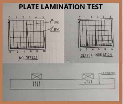
Ultrasonic Testing for laminations in plates
Ultrasonic Testing for laminations in plates - A normal probe is brought into contact with the face of the plate through a couplant. The height of the back wall echo is kept at a fixed amplitude (50% or above F.S.H.)
Any drop 1n back wall echo is considered to be caused by defective area. Usually, the plate is scanned along grid lines only and wherever the back wall echo falls beyond a set level or when a defect indication is present, the adjacent area is also scanned to determine the area of defect. Some times angle beam technique is also used to detect the presence of defects that are not oriented parallel to the surface.
When a number of plates are to be tested by an ultrasonic test, a plate scanner can be used. Flaw Detector, probe, etc. are fitted on a trolley and the probe is coupled to the plate through a water column. Testing can be done at a higher speed and wear & tear to the probe can be eliminated by using a plate scanner.
SOME PRACTICAL APPLICATIONS OF ULTRASONIC TESTING
Thickness Gauging
Ultrasonics is being widely used in thickness gauging in involved in chemical and fertilizer plants, ships, pipelines, storage tanks, etc. Although a digital read-out thickness meter can be used for this purpose, using an Ultrasonic Flaw Detector can provide additional information that will avoid the possible errors while using a thickness meter.
Whenever small (compared to beam size) defects are encountered, the presentation on a flaw detector shows a defect indication and a back wall indication. Using a thickness meter will only show the depth of the defect. Moreover, a heavily corroded surface will show a broader - indication on the CRT whereas this info motion cannot be obtained with a thickness meter. Both the flaw detector and the thickness meter use the pulse-echo method with single crystal probes as transmitter and receiver or double crystal probes, one acting as a transmitter and the other as a receiver.
The instrument is calibrated in the usual manner for the distance required. The gain setting. is adjusted to receive an echo of adequate height. Gain may be required to be in creased on the actual job, as in the case of a badly pitted surface while calibrating the distance axis, care has to be taken to ensure that test block has the same velocity. as that of the test specimen.


No comments:
Post a Comment
Please do not enter any spam link in the comment box