WHAT IS SAW WELDING, TYPES, USES, AND ITS ADVANTAGE AND DISADVANTAGE
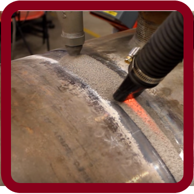
In this process, an arc is maintained between a continuously fed bare wire electrode and the workpiece underneath a mass of fusible granular flux. The flux is dispensed over the joint area and the wire is fed into it. The arc which forms melts a proportion of the flux, which protects the weld pool from atmospheric contamination, shields the remaining unmelted flux acts as a shield for the arc itself. The power source may provide either alternating or direct current. Highest deposition. rates are obtained with electrode negative, but control of bead shape and penetration is better with electrode positive.
Submerged arc welding flux consists of a mixture of minerals (for e.g. Aluminum, calcium, manganese .oxides with silica and calcium fluoride) that have been agglomerated, sintered or fused together to form a coarse powder. Alloying elements are sometimes added in order to compensate for losses that would otherwise occur during the metal transfer. Occasionally, the whole alloy addition is made via the flux, a carbon steel wire being used, but this is an undesirable practice, since it may lead to irregularities in weld bead composition.
Submerged arc welding is capable of high deposition rates and of making weld runs of substantial thickness. The amount of metal that may be deposited in a single run is limited partly by practical considerations and partly by the need to avoid an excessive coarse grain size. The impact strength of coarse-grain carbon and low alloy steel welds in the as-welded or stress relieved condition will not always meet engineering requirements for the more severe applications such as pressure vessels. The submerged arc process is applicable to carbon, low alloy, and high alloy steel. It is used in all engineering fields and may be applied manually or automatically, generally the latter. It may be used in the flat or horizontal positions, but not vertical overhead welding.
SAW WELDING USED IN-
• Power Plant Structures
• Special Purpose Cars
• Windmill Towers…….
Definition & schematic
Submerged arc welding (SAW) is a common arc welding process.
The first patent on the submerged-arc welding (SAW) process was taken out in 1935 and covered an electric arc beneath a bed of granulated flux. Originally developed and patented by Jones, Kennedy, and Rothermund, the process requires a continuously fed consumable solid or tubular (metal cored) electrode.
The molten weld and the arc zone are protected from atmospheric contamination by being "submerged" under a blanket of granular fusible flux consisting of lime, silica, manganese oxide, calcium fluoride, and other compounds. When molten, the flux becomes conductive and provides a current path between the electrode and the work.
This thick layer of flux completely covers the molten metal thus preventing spatter and sparks as well as suppressing the intense ultraviolet radiation and fumes that are a part of the shielded metal arc welding (SMAW) process.
Other Details
SAW is normally operated in the automatic or mechanized mode, however, semi-automatic (hand-held) SAW guns with pressurized or gravity flux feed delivery are available. The process is normally limited to the flat or horizontal-fillet welding positions (although horizontal groove position welds have been done with a special arrangement to support the flux). Deposition rates approaching 45 kg/h (100 lb/h) have been reported — this compares to ~5 kg/h (10 lb/h) (max) for shielded metal arc welding. Although currents ranging from 300 to 2000 A (440V)are commonly utilized, currents of up to 5000 A have also been used (multiple arcs).
Single or multiple (2 to 5) electrode wire variations of the process exist. SAW strip-cladding utilizes a flat strip electrode (e.g. 60 mm wide x 0.5 mm thick). DC or AC power can be used, and combinations of DC and AC are common on multiple electrode systems. Constant voltage welding power supplies are most commonly used; however, constant current systems in combination with a voltage sensing wire-feeder are available.
Components detail of SAW
WELDING HEAD
It feeds flux and filler metal to the welding joint. Electrode (filler metal) gets energized here.
FLUX
The granulated flux shields and thus protects the molten weld from atmospheric contamination. The flux cleans weld metal and can modify its chemical composition also. The flux is granulated to a definite size. It may be of fused, bonded or mechanically mixed type. The flux may consist of fluorides of calcium and oxides of calcium, magnesium, silicon, aluminum, and manganese. Alloying elements may be added as per requirements. Substances evolving large amounts of gases during welding are never mixed with the flux. Flux with fine and coarse particle sizes is recommended for welding heavier and smaller thickness respectively.
ELECTRODE
SAW filler material usually is a standard wire as well as other special forms. This wire normally has a thickness of 1.6 mm to 6 mm (1/16 in. to 1/4 in.). In certain circumstances, the twisted wire can be used to give the arc an oscillating movement. This helps fuse the toe of the weld to the base metal.
SAW filler material usually is a standard wire as well as other special forms. This wire normally has a thickness of 1.6 mm to 6 mm (1/16 in. to 1/4 in.). In certain circumstances, the twisted wire can be used to give the arc an oscillating movement. This helps fuse the toe of the weld to the base metal.
The electrode composition depends upon the material being welded. Alloying elements may be added to the electrodes. Electrodes are available to weld mild steels, high carbon steels, low and special alloy steels, stainless steel and some of the nonferrous of copper and nickel. Electrodes are generally copper coated to prevent rusting and to increase their electrical conductivity. Electrodes are available in straight lengths and coils. Their diameters maybe 1.6, 2.0, 2.4, 3, 4.0, 4.8, and 6.4 mm.
The approximate value of currents to weld with 1.6, 3.2 and 6.4 mm diameter electrodes are 150–350, 250–800 and 650–1350 Amps respectively.
Welding operation of SAW
The flux starts depositing on the joint to be welded. Since the flux when cold is non-conductor of electricity, the arc may be struck either by touching the electrode with the workpiece or by placing steel wool between electrode and job before switching on the welding current or by using a high-frequency unit. In all cases, the arc is struck under a cover of flux. Flux otherwise is an insulator but once it melts due to heat of the arc, it becomes highly conductive and hence the current flow is maintained between the electrode and the workpiece through the molten flux. The upper portion of the flux, in contact with the atmosphere, which is visible remains granular (unchanged) and can be reused. The lower, melted flux becomes slag, which is waste material and must be removed after welding.
The electrode at a predetermined speed is continuously fed to the joint to be welded. In semi-automatic welding sets the welding head is moved manually along the joint. In automatic welding, a separate drive moves either the welding head over the stationary job or the job moves/rotates under the stationary welding head.
The arc length is kept constant by using the principle of a self-adjusting arc. If the arc length decreases, arc voltage will increase, arc current and therefore burn-off rate will increase thereby causing the arc to lengthen. The reverse occurs if the arc length increases more than the normal.[citation needed]
A backing plate of steel or copper may be used to control penetration and to support large amounts of molten metal associated with the process.
Process Variables of SAW
• Wire feed speed (main factor in welding current control)
• Welding Current
• Arc voltage
• Travel speed
• Electrode stick-out (ESO) or contact tip to work (CTTW)
• Polarity and current type (AC or DC) and variable balance AC current
application..............................................
• Carbon steels (structural and vessel construction)
• Low alloy steels
• Stainless steels
• Nickel-based alloys
• Surfacing applications (wear-facing, build-up, and corrosion-resistant overlay of steels)
Advantages of SAW Welding
• High deposition rates (over 45 kg/h (100 lb/h) have been reported).
• High operating factors in mechanized applications.
• Deep weld penetration.
• Sound welds are readily made (with good process design and control).
• High-speed welding of thin sheet steels up to 5 m/min (16 ft/min) is possible.
• Minimal welding fume or arc light is emitted.
• Practically no edge preparation is necessary depending on joint configuration and required penetration.
• The process is suitable for both indoor and outdoor works.
• Welds produced are sound, uniform, ductile, corrosion-resistant and have good impact value.
• Single-pass welds can be made in thick plates with normal equipment.
• The arc is always covered under a blanket of flux, thus there is no chance of spattering of the weld.
• 50% to 90% of the flux is recoverable, recycled and reused.
Limitations of SAW Welding
• Limited to ferrous (steel or stainless steel) and some nickel-based alloys.
• Normally limited to the 1F, 1G, and 2F positions.
• Normally limited to long straight seams or rotated pipes or vessels.
• Requires relatively troublesome flux handling systems.
• Flux and slag residue can present a health and safety concern.
• Requires inter-pass and post-weld slag removal.
• Requires backing strips for proper root penetration.
• Limited to high thickness materials.
TYPES OF SAW WELDING
1st- Single Wire
- Single wire welding is the most widely used SAW method.
- DC power source is used.
- A small diameter produces a higher deposition at the same rate.
2nd- win wire
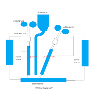
- The tandem twin process involves two-wire heads placed in sequence.
- Both AC and DC sources can be used.
- With the use of a 4x2.5 mm diameter, the wire deposition rate of up to 38kg/h can be achieved.
3rd - Tandem
- For twin wire welding, two wires are connected to the same power source.
- DC power source is used
- It offers up to 30% higher deposition rates and can be used at higher current and speed.
- Very high welding speed can be achieved in fillet welding.
4th- Tandem twin
- The tandem twin process involves twin wire heads placed in sequence. Both AC and DC sources can be used.
- With the use of 4x2.5nn diameter wire deposition rates of up to 38kg/h can be achieved.
- he tandem twin process involves two twin-wire heads placed in sequence.
- Both AC and DC sources can be used.
- With the use of 4x2.5nn diameter wire deposition rates of up to 38kg/h can be achieved.
5th- Multiwire
- In the multiwire technique, up to 6 wires can be used together, each with their own power source.
- The lead wire is usually DC+ polarity with the trailing wires being AC.
- Speed of up to 2.5m/min can be achieved giving a maximum deposition rate of 90kg/h.
- This technique is particularly suitable for longitudinal pipe welding.
Automatic v/s semi-automatic SAW
Fully Automatic
• Flux Fed Mechanically ahead of the Arc
• Wire Fed Automatically
• Arc Length Controlled automatically
Semi-Automatic
• Wire Feed and Arc Length controlled Automatically
• Welder Moves the Welding Gun
• Flux feed may be by gravity flow
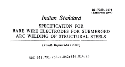
Is 7280-1974 (see detail on "
AWS Designation
How to read AWS designation
In AWS A.5.17 and AWS A5.23 the first part of the designation describes the flux type and may comprise up to six digits depending upon whether the flux is supplied with the tensile strength expressed in increments of 10 megapascals (two numbers where 43 represents 430MPa) or in pounds per square inch (1 digit i.e. 6 represents 60,000psi).
The first digit, the letter 'F', identifies the consumable as a submerged arc welding flux, the next letter 'S' is only included if the flux is made from or includes crushed slag. The omission of this letter 'S' indicates that the flux is unused and contains no crushed used flux introduced either by the flux manufacturer or the welding fabricator.
The next one or two digits specify the minimum tensile strength as explained above and this is followed by 'A' or 'P' for whether the test results were obtained in the as-welded, the A condition or post-weld heat-treated, the P condition.
Impact test requirement
The last digit identifies the minimum temperature at which a Charpy-V impact value of 27J can be achieved as in Table 1 below.
In AWS A5.17 there is a total of eleven wires, split into 3 groups of low, medium and high manganese. first digit, 'E', identifies the consumable as a bare wire electrode. If supplemented by 'C' the wire is a composite (cored) electrode. The composition of the solid wire is obtained from an analysis of the wire. However, since the composition of a cored wire may be different from that of its weld deposit the composition must be determined from a low dilution weld deposit made using a specific, named flux.
The next letter, 'L', 'M' or 'H' indicates a low (0.6% max), medium (1.4% max) or high (2.2% max) manganese content. This is followed by one or two digits that give the nominal carbon content. An optional letter 'K' indicates a silicon killed steel. There are a final two or three optional digits identifying the diffusible hydrogen in ml/100gms weld metal, H16, H8 or H4.
A full designation for a carbon steel flux/wire combination could, therefore, be F6P5-EM12K-H8. This identifies this as being a solid wire with a nominal 0.12% carbon, 1% manganese and 0.1 to 0.35% silicon capable of achieving an ultimate tensile strength of 60 k.p.i. (415MPa), Charpy-V impact strength of 27J at -50°F (-46°C) in the post-weld heat-treated condition.
Table 1: Impact Test Requirement
Granular flux used in welding is a type of granular insulative material that is made up of numerous small particles. In Submerged Arc Welding (SAW), the granular flux provides a blanket over the weld, which protects against sparks and spatter. In SAW, the granular flux is frequently the means for achieving high deposition rates. The flux is also instrumental in producing the type of quality weld that is common in this particular welding process.
In addition to providing a protective cover over the weld, the flux shields and cleans the molten puddle. The flux also affects the chemical composition of the weld metal, the weld bead shape, and the mechanical properties of the weld.
Another function of granular flux is to act as a barrier that holds the heat in and concentrates the heat into the weld area to promote deep penetration.
Types of SAW fluxes
The methods used to manufacture fluxes determine the flux types. There are fused fluxes, bonded fluxes, agglomerated fluxes, and mechanically mixed fluxes.
When manufacturing fused fluxes, raw materials are melted into a liquid state with a high-temperature electric furnace. The material is then cooled and crushed or ground into the desired particle size.
When making bonded fluxes, the ingredients are dry mixed, then glued together with a liquid binder. This binder may be a liquid such as sodium silicate. After the particles are bonded, they are baked and then sifted through a sieve to attain flux particles of the desired size.
Agglomerated fluxes are manufactured much the same way that bonded fluxes are made. However, instead of a liquid binder, a ceramic binder is used. Higher drying temperature is used, too. (The higher drying temperature limits the use of deoxidizers and alloy elements.)
Fluxes that are mechanically mixed are combinations of two or more bonded or agglomerated fluxes. Although mechanically mixed fluxes make it possible to create special mixtures for more sensitive welds, these fluxes may separate during storage, use, and recovery of flux.
Fused Flux
Advantages of fused fluxes include:
The non-hygroscopic flux particles do not absorb moisture and, therefore, any surface moisture can be eliminated merely by drying the particles at a low-temperature oven setting of 300 degrees F.
Low-temperature drying of condensation on the fused flux particles provides better protection against hydrogen cracking.
Flux particles create welds that are chemically consistent.
Recycling of fused flux particles through the flux recovery systems can be achieved without losing sizing or composition.
A disadvantage of fused fluxes is that the high temperature used during the manufacturing process makes it difficult to add alloys and deoxidizers.
Bonded flux
Advantages of bonded fluxes include:
Deoxidizers are present in bonded fluxes, protecting against rust and mill scale. These deoxidizers also help to prevent welds from becoming porous.
Alloys can be added to bonded fluxes. Alloy elements may improve the chemical and mechanical properties of the flux.
Bonded fluxes allow for a thicker flux layer when welding.
Bonded fluxes can be identified by color.
Bonded fluxes typically provide better peeling properties than fused fluxes.
There are at least two disadvantages of using bonded fluxes. These are:
They absorb moisture.
They can change in composition due to segregation or loss of fine particle size.
Basicity Index
Perhaps the most convenient method of classifying, however, is by reference to the 'basicity index' (BI) of the flux. The index is calculated by dividing the sum of the percentages of the basic constituents by the sum of the acid constituents. Calcium, magnesium, sodium, potassium and manganese oxides, calcium carbonate and calcium fluoride are the basic constituents of a flux; silica and alumina the acid constituents. Acid fluxes have a basicity index of 0.5 to 0.8; neutral fluxes 0.8 to 1.2; basic fluxes 1.2 to 2.5 and highly basic fluxes 2.5 to 4.0. The basicity of flux has a major effect on the weld metal properties, most importantly the notch toughness. As a general rule the higher the basicity the higher the notch toughness.
Neutral fluxes are designed to have little or no effect on the chemical analysis of the weld metal and therefore on the mechanical properties. They contain low silica, calcium silicate and alumina and do not add significant amounts of silicon and manganese to the weld.
The acid fluxes contain substantial amounts of silica, silicates in the form of calcium and/or manganese silicate and manganese oxide. These fluxes react with the weld pool and will raise both silicon and manganese content of the weld together with high oxygen content. The result of this is that the toughness of the weld is poor but the fluxes will tolerate rusty surfaces, will detach easily and give a good weld appearance. They are especially useful for single-pass high-speed welding such as fillet welding of the web to flange girder joints.
The basic fluxes fill much the same role in submerged arc welding as basic coatings do in manual metal arc welding. They have low silica content and are composed of varying amounts of calcium carbonate and/or fluoride, alumina, calcium, manganese and magnesium oxides and rutile.
Storage of SAW Flux
Just as stick welding electrodes readily pick up moisture from the surrounding atmosphere, the same applies to bonded welding fluxes that are comprised mostly of dry, powdered ingredients. As described above, the purpose of flux is to clean and shield the weld area from impurities. If moisture has contaminated the flux, hydrogen is released into the metal when heat is applied. When the weld cools, it can become brittle, crack and/or develop pinholes. Moisture-contaminated flux can also accelerate corrosion to certain metals like aluminum and must be kept dry throughout the welding process.
Welding flux holding ovens and rebake ovens are an indispensable addition to any submerged arc welding operation to help ensure quality welds.
this type of flux is non-hygroscopic (does not absorb
can be removed at a low-temperature oven setting of 300°F. (150 ºC)
moisture from the air). Any surface moisture on the particles
Bonded Type —
this type of flux is hygroscopic (absorbs moisture from the
air) and is comprised of a combination of dry ingredients thatare glued together with a liquid binder, then baked at a low
oven temperature.
Agglomerated Type —
this type of flux is hygroscopic and is manufactured in the same way as bonded fluxes only a ceramic binder is used instead of a liquid binder.
Pre-Mixed Type—
this type of flux is hygroscopic and is simply a combination of two or more bonded or agglomerated fluxes.Variations of saw process
The submerged arc welding process may be varied in a number of ways to give it more capabilities. These include, but are not limited to, varying the number of wires and power sources, adding the iron powder to the flux, and using a strip electrode for surfacing.
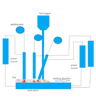
Multi-wire systems offer advantages because the use of more electrodes can improve deposition rates and travel speeds. The utilization of more than one electrode in submerged arc welding may be accomplished with either a single power source or separate power sources for each wire.
The use of multiple power sources with two or more electrodes allows for the utilization of different polarities on the electrodes. Also, with separate power sources for two electrodes, alternating current may be used on one, while direct current is used on the other electrode. Typically, when three wires are used in the tandem position (one electrode is placed in front of the other), alternating current is used. The electrodes are connected to three-phase power systems, which are used for making high-speed longitudinal seams on large pipes and fabricated beams.
Adding iron powder to the flux increases deposition rates of submerged arc welding, but it does not decrease the properties of the weld metal.
The utilization of a strip electrode for surfacing may be done to save money. This particular welding system uses the strip electrode and flux to make a corrosion-resistant overlay on a less expensive base material such as stainless steel. During this procedure, a wide, uniform bead is produced that has minimum penetration. The uniform bead is necessary to provide a smooth overall surface. The strip welding system is often used for overlaying the inside of vessels. The flux that is used in strip surfacing is made specifically for that purpose.
Arc start
• With still wool or iron powder
• Sharp wire start
• Scratch start
• Molten flux start
• Wire retract start
• High-Frequency start
Electrode Polarity in SAW
The deepest penetration is usually obtained with the direct current electrode positive (DCEP) polarity which also gives the best surface appearance, bead shape, and resistance to porosity. Direct current electrode negative (DCEN) polarity gives an increased burnoff rate and decreased penetration as maximum heat is developed at the tip of the electrode instead of at the surface of the plate. For this reason, DCEN polarity is often used for surfacing or cladding and for other applications where high deposition rates are required, with minimum dilution from the parent material. The flux/wire consumption ratio is less with DCEN polarity than with DCEP so the transfer of alloying elements from the flux is reduced.
In changing from DCEP to DCEN polarity, some increase in arc voltage may be necessary to obtain a comparable bead shape. Alternating current requires a voltage about halfway between DCEP and DCEN polarity and is particularly useful when arc blow is a problem. It is often used in tandem arc systems in which DCEP is used on the leading electrode and AC on the trailing electrode in order to minimize magnetic interaction between the two arcs.
Efficiency in SAW
The efficiency of Solid Wires for SAW
In submerged arc welding there is no spatter loss and an efficiency of 99% may be assumed. The only loss during welding is the short piece the operator must clip off the end of the wire to remove the fused flux that forms at the termination of each weld. This is done to assure a good start on the succeeding weld.
The increased weld deposition rate
The Weld metal Deposition rate, in-unit of kg/arc hour, is measured by the amount of weld metal deposited at a given current level. In a single pass or single pass per side welds, the welding speed per meter of joint increases with the SAW process. Likewise, in multi-pass welds, the number of passes required to complete the joint decreases considerably and the time to complete the joint reduces.
To illustrate, let us compare the deposition rate of MMAW, MIG Welding and SAW processes :
• The deposition rate of 5.0 mm, MMAW E7018 electrode at 220 amps is 2.1 kgs/arc hour
• The deposition rate for 1.2 mm, MIG wire(ER70S-6) at 250 amps is 4.2 kg/arc hour.
• The deposition rate for 1.6mm, SAW EH14 electrode at 400 amps is 6.2 kgs/arc hour.
Increased depth of penetration
The depth of penetration, in mm, is measured by the depth of fusion on the unprepared surface, at a given current level and given welding speed. Higher the depth of penetration, less is the need for joint preparation or back gouging. Multiple pass welds can be reduced to a single pass or single pass per side welds, with less or no joint preparation or back gouging. Thus the joints can be completed faster. Let us compare the depth of penetration of MMAW, MIG welding, and saw processes.
• The depth of penetration for 5.0 mm E7018 electrode at 220 amps is 2mm.
• The depth of penetration for 1.2mm, MIG wire(ER70S6) at 250 amps is 3.5 mm.
• The depth of penetration for 1.6mm, SAW EH14 electrode at 400 amps is 5 mm.
Welding Current -SAW
It controls:
• The Melting rate of the electrode – Deposition Rate
• The Depth of Penetration – the extent of dilution of the weld metal by the base metal
The high current causes excessive weld reinforcement, high narrow bead and undercut.
Low current gives an unstable arc, inadequate penetration and overlapping
arc voltage
Increasing Voltage :
• Produces a flatter and wider bead
• Increases flux consumption
• Increases resistance to porosity caused by rust or scale
• Increases pickup of an ally from the flux
Excessively High Voltage:
• Produces a hat-shaped head that is subject to cracking
• Produces poor slag removal in groove welds
• Produces a concave filler weld that may be subjected to cracking
• Increases undercut on fillet welds
Lowering the voltage produces a high narrow bead with poor slag removal
Speed of arc travel
Increasing the welding speed
• Lesser penetration
• Lesser weld reinforcement
• Lower heat input per unit length of the weld
Excessively high speed
• Decreases fusion between the weld deposit and the parent metal.
• Increases tendencies for undercut, arc blow, porosity, irregular bead shape.
Slow speed results in poor penetration
Electrode Stick – out in SAW Welding
- It is also termed as electrode extension – length of the electrode between the end of the contact tube and the arc
- The longer the stick-out:
- The greater the amount of heating
- Higher deposition rate
- Decreased penetration rate
- 75 mm for 2.0,2.4 and 3.2 mm wire diameter
- 125 mm for 4.0, 4.8 and 5.6 mm wire diameter.
video to summarize saw---






No comments:
Post a Comment
Please do not enter any spam link in the comment box